Outputs are devices that allow you to manipulate the environment and are a crucial component of a feedback loop in an automation system. Below are some common output devices that can be easily incorporated into an automation system.
If you want to begin learning about and developing automation systems, I recommend my software, Mycodo, and a single board computer.
Speed-Controlled Duct Fans
Duct fans are used to move air through circular ducts, often used with indoor hydroponic and mushroom cultivation systems, but there are a number of other uses. Electrically-controlled fans allow the speed to be controlled, typically from ~20% – 100%. Additionally, these fans also typically have a tachometer pin to be able to measure the fan blade speed. This can be useful for verifying the fan blade is actually spinning when it’s instructed to turn on or to gauge how much resistance the fan is encountering in the duct (for example, determining when a filter needs to be replaced based on reduction of fan blade RPM over time as the filter becomes clogged).
TerraBloom
TerraBloom makes a number of quality speed-controlled fans that also have a tachometer wire to measure actual fan blade rotational speed. This is useful to be able to verify the fan is working when instructed to turn on as well as measuring resistance to air movement. This can be useful, for instance, to determine when a filter needs replacing.
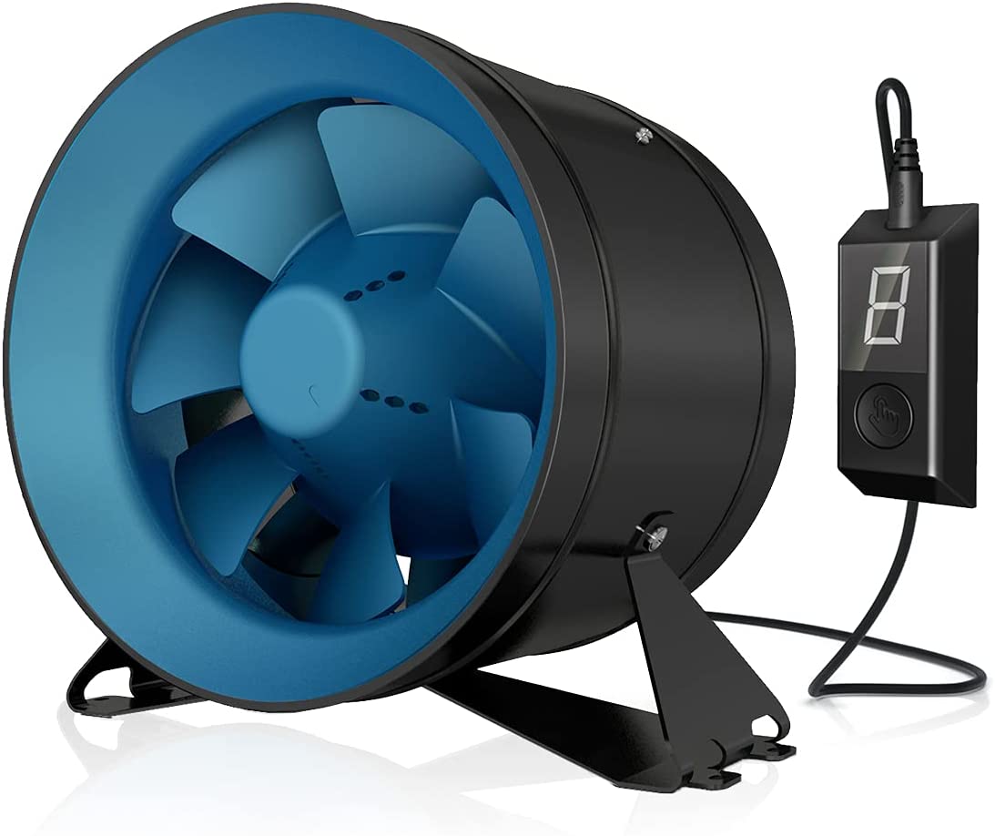
ECMF-100 4 Inch Inline Duct Fan
- Airflow: 141 CFM
- Watts at Max Speed: 21 W
ECMF-150 6 Inch Inline Duct Fan
- Airflow: 288 CFM
- Watts at Max Speed: 36 W
ECMF-200 8 Inch Inline Duct Fan
- Airflow: 569 CFM
- Watts at Max Speed: 74 W
ECMF-250 10 Inch Inline Duct Fan
- Airflow: 946 CFM
- Watts at Max Speed: 126 W
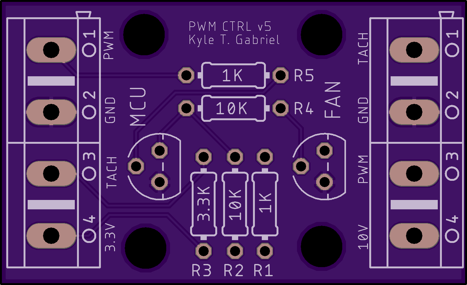
Speed Control Board for Terrabloom EC Duct Fans
This is a custom PCB I designed to both control the speed of Terrabloom EC fans and be able to measure from the tachometer pins. It converts a 3.3-volt or 5-volt PWM signal from a single board computer (SBC), such as a Raspberry Pi, or a microcontroller (MCU), into a 10-volt PWM signal to control the fan speed. The tachometer is an open collector and can be measured by the SBC or MCU. You can then use your custom code or Mycodo to control the speed of your fans and measure the speed the fan blades are rotating.
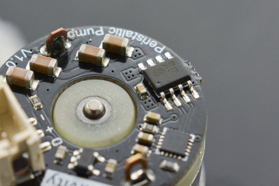
Peristaltic Pumps
Peristaltic pumps are fluid pumps that allow precise dispensing of liquids. Due to their design, they also prevent self-siphoning that are common with centrifugal and some diaphragm pumps.
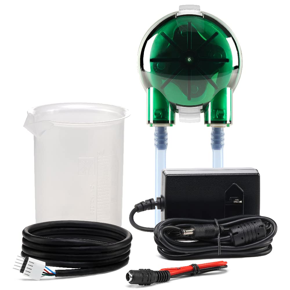
Atlas Scientific All-In-One Pump Kit
Atlas Scientific makes all-in-one peristaltic pumps combined with a circuit board to allow simple control of the pump without needing to incorporate external control boards or relays. The microcontroller or computer sends the desired amount to be pumped and the circuit board determining how long the pump needs to run to dispense that amount. Their pumps are a bit pricey, but are a good option if you want something that can be dropped into a project and begin working immediately without much effort writing code for calibrating, calculating dispense times, etc.

Atlas Scientific Dosing Pump Kit
- Flow rate: 0.5 ml to 105 ml/min
- Accuracy: ± 1 %
- Motor Input Voltage: 12 VDC
- Modes of operation: Continuous dispensing, Volume dispensing, Constant flow rate, Dose over time mode and Dispense at startup
- Calibration: Single point
Additional pumps alone are available here.
Atlas Scientific Large Dosing Pump Kit
- Flow rate: 10 ml – 750 ml/min
- Accuracy: ± 1 %
- Motor Input Voltage: 24 VDC
- Modes of operation: Continuous dispensing, Volume dispensing, Constant flow rate, Dose over time mode and Dispense at startup
- Calibration: Single point
Gravity All-In-One Pump Kit
Gravity also makes an all-in-one peristaltic pump and control board, which can be controlled with a single control pin via a PPM signal. I am currently exploring adding an Output in Mycodo to control this pump.
Gravity Peristaltic Pump Kit
- Flow rate: ≥45 ml/min
- Motor Input Voltage: 5 VDC – 6 VDC
- Maximum Continuous Operating Current: 1.8 A
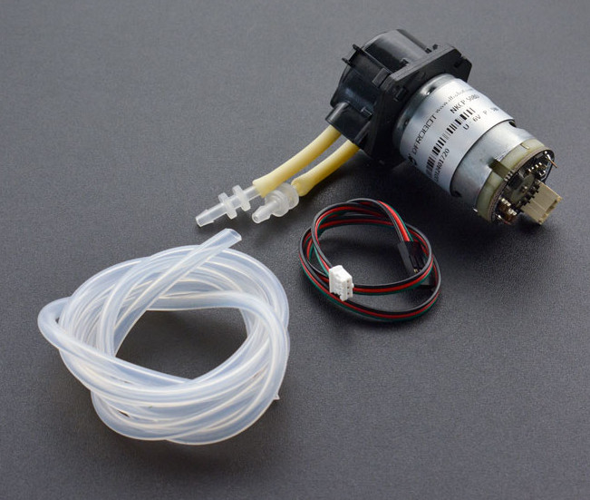
DIY Peristaltic Pumps
Peristaltic pumps can also be bought by themselves and connected to a motor driver or relay to power them. This is a cheaper alternative to Atlas Scientific products, but requires additional parts and effort to develop an electrical control system for the pumps. The L298N is a great inexpensive motor driver that can control DC and stepper motors with a microcontroller or single board computer. If you’re using a single board computer like the Raspberry Pi, you can set up a L298N Peristaltic Pump Output in the Mycodo software to calibrate and control generic pumps with the L298N motor driver.
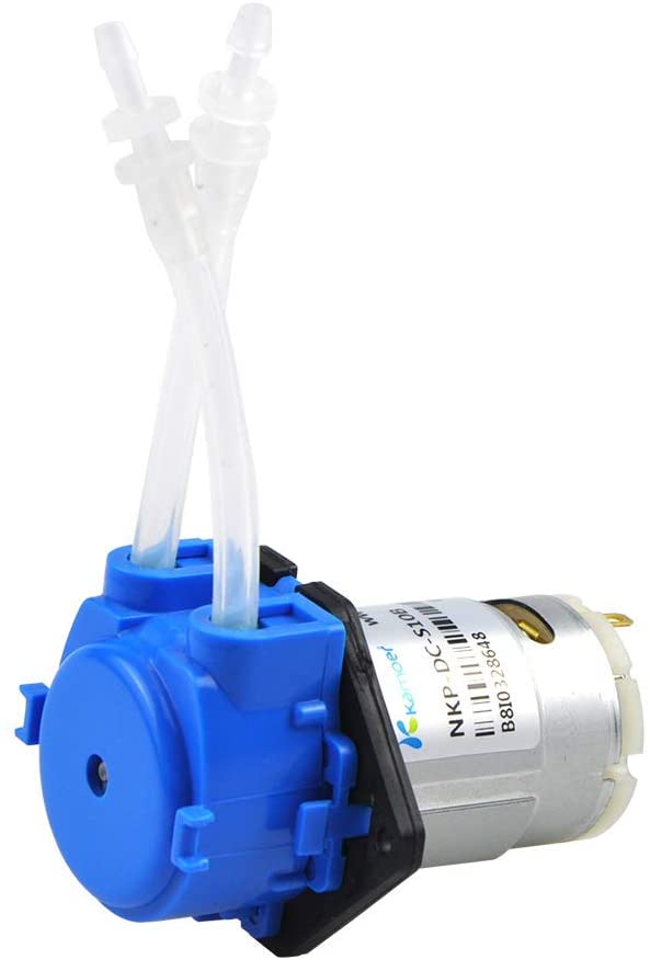
Small Peristaltic Pump
- Power: 12 Volt DC
- Current Draw: 0.25 A
- Flow Rate: ≥ 70 ml/min
- Tube Size: 3 mm ID x 5 mm OD
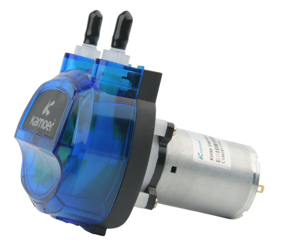
Medium Peristaltic Pump
- Power: 12 Volt DC
- Flow Rate: 500 ml/min
- Tube Size: 4 mm ID × 7.2 mm OD

Large Peristaltic Pump
- Power: 24 Volt DC
- Current Draw: 1.8 A
- Flow Rate: 1800 ml/min
- Tube Size: 7.9 mm ID × 12.7 mm OD
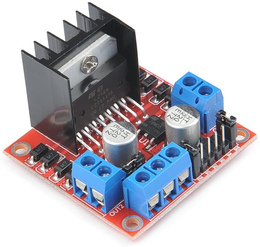
L298N Motor Driver
- Can drive 2 motors
- Motor Types: DC Motor, DC Stepper
- Drive Voltage: 5 – 32 Volts DC
- Drive current: 2 A (for each DC motor)
This can be used to drive the above peristaltic pumps. You will need to supply either 12 or 24 volts, depending which pump you use. Each L298N motor driver board can drive 2 motors. The motor driver enables controlling motor direction (forward/backward) and speed.
Relays
Relays allow the switching on and off of a voltage source by a voltage signal. The relay isolates the two voltages so there is no crossover of electricity that may be damaging to the control device. Typically the control device uses a low voltage signal (usually 3.3 – 24 direct current volts) to control a much higher voltage, such as your house mains voltage that operate household appliances (typically 120 or 240 alternating current volts).
There are two general types of communication to control relays, wired and wireless. Wired control of relays is the safest wince there is a physical connection to control the relay. The use of wireless signals to control relays means there won’t be physical wires needed to be routed from your controller to the relay, but it also introduces a host of additional points of failure, from poor signal, interference, faulty router, etc. For any critical application, such as keeping animals and crops alive, or regulating high-value commodities, I will always recommend wired over wireless control. But, for prototyping, or less critical systems, wireless relays are a great option.
Wireless Pre-Made Controllable Outlet Devices
These are fully-built devices that let you control power to household outlets, without having to construct anything. They’re the safest to use, since you aren’t building anything that requires working with wiring or mains voltages. You simply plug in a device to the outlet, connect a microcontroller (MCU) or single board computer (SBC), then send a signal to the outlet box from the MCU or SBC and the outlet turns on or off.
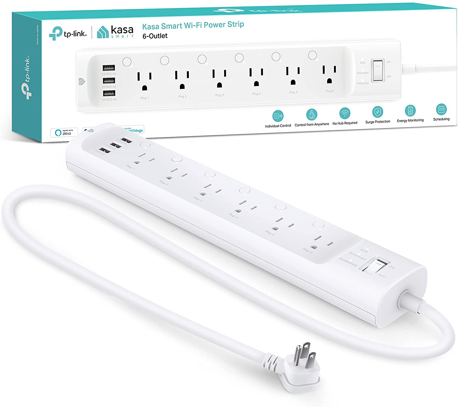
Kasa HS300 6-Outlet WiFi Power Strip
- Outlets: 6 individually controlled
- Extra Power: 3 USB
- Connectivity: Wireless (WiFi)
- Control: Mycodo, Android, iOS, Alexa, Google Home
- Energy Usage Monitoring: Yes
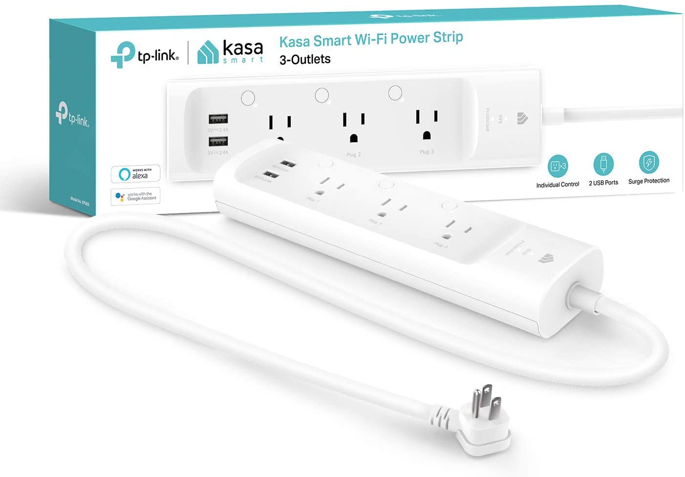
Kasa KP303 3-Outlet WiFi Power Strip
- Outlets: 3 individually controlled
- Extra Power: 2 USB
- Connectivity: Wireless (WiFi)
- Control: Mycodo, Android, iOS, Alexa, Google Home
- Energy Usage Monitoring: No
This power strip is similar to the HS600, except it does not have the ability to monitor energy/power usage and it has half as many controllable outlets.

Kasa KP115 WiFi Power Plug
- Outlets: 1 individually controlled per plug
- Connectivity: Wireless (WiFi)
- Control: Mycodo, Android, iOS, Alexa, Google Home
- Energy Usage Monitoring: Yes
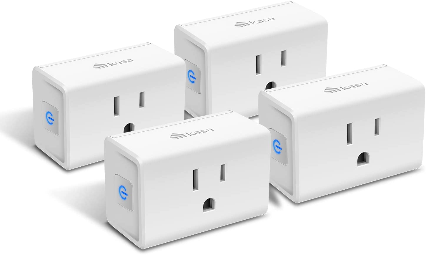
Kasa EP10P4 Wifi Power Plug
- Outlets: 1 individually controlled per plug
- Connectivity: Wireless (WiFi)
- Control: Mycodo, Android, iOS, Alexa, Google Home
- Energy Usage Monitoring: No
This plug is similar to the KP115/KP125, above, except it does not have the ability to monitor energy/power usage. Without this feature alone, it is significantly less expensive.
Wired Relay Modules
There are a number of relay module boards on the market that make interfacing with microcontrollers or single board computers simple, and allow controlling 120 or 240 mains voltages. These can be used to switch power to any appliance or device that normally plugs into a household outlet. There needs to be extra caution when working with these modules, since mains voltages can be very dangerous.
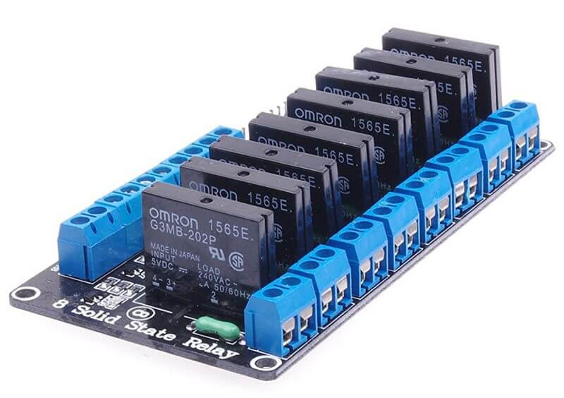
Solid State Relay Module (8 Channels)
- Relays: 8 Solid State Relays
- Switched Voltage: 0 – 240 VAC, 50/60 Hz
- Current: 2 A per relay
- Control Voltage: 3.3 or 5 VDC
Also available in:
4 Channel Relay Module
2 Channel Relay Module
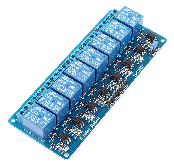
Mechanical Relay Module (8 Channels)
- Relays: 8 Solid State Relays
- Switched Voltage: 0 – 240 VAC, 50/60 Hz
- Current: 10 A per relay
- Control Voltage: 3.3 or 5 VDC
Also available in:
4 Channel Relay Module
2 Channel Relay Module
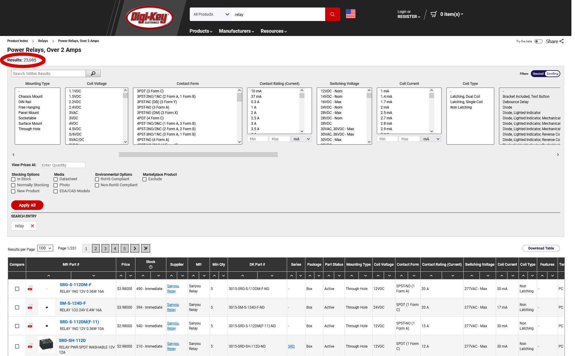
Individual Relay Components
There are a huge number of relays available to choose from, and the right relay will depend on the application. A relay should be chosen based on its specifications and the characteristics of the device doing the switching and the device being switched. Electronics suppliers provide ways to specify these characteristics in order to filter for the appropriate relays (see screenshot, below).
Motors
There are several types of motors that can be controlled, AC motors, DC motors, stepper motors, servo motors, etc. Each is suited for a specific application and requires different hardware for control. Most motors require the use of a motor driver if you want to control speed. A motor can be turned on and off simply by switching power to it with a relay.
Digital Potentiometers
Digital potentiometers are digital-to-analog converters (DACs), allowing you to control resistance digitally. These are handy if you want to replace a physical potentiometer and control it via a microcontroller or single board computer.
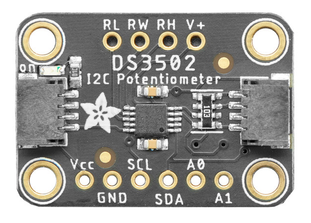
DS3502 Digital Potentiometer
- Range: 0 – 10 kOhm
- Resolution: 7-bit
- Analog Voltage Controlled: 4.5-15.5V